
Design
Inredning
Tips
Natursköna fototapeter: Konst på väggen som inspirerar
Fototapeter har revolutionerat heminredning genom att erbjuda konstnärliga och inspirerande lösningar för att förvandla ditt hem. En av de mest fascinerande aspekterna av fototapeter är deras förmåga att skapa en illusion av att du befinner dig i en helt annan plats eller värld. Denna artikel kommer att utforska den magiska världen av natursköna fototapeter och […]
Read More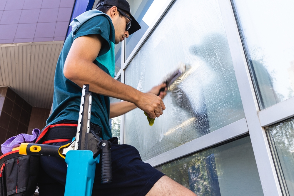
Tips
Få kristallklara fönster med professionell fönsterputsning i Stockholm
Att ha rena och klara fönster i ditt hem är inte bara estetiskt tilltalande, det kan även påverka din livskvalitet. Med åren kan fönstren bli smutsiga och dammiga, och det kan vara en utmaning att få dem riktigt rena igen. Det är här professionell fönsterputsning kommer in i bilden. Om du bor i Stockholm och […]
Read More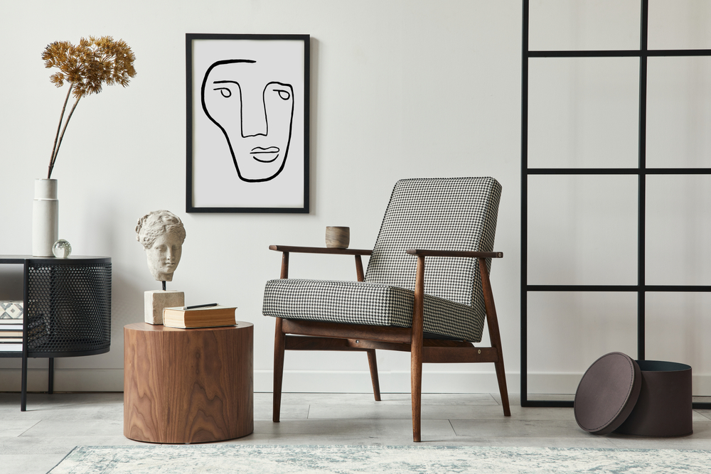
Inredning
Tips
Hemtrevlig retro – Återskapa det förflutna med stil
Att inreda sitt hem med en retrostil innebär mer än bara att välja ut gamla föremål; det handlar om att skapa en känsla som andas historia och personlighet. Retrostilen kan variera från 50-talets färgglada optimism till 70-talets jordnära palett och geometriska former. Men hur skapar man en hemtrevlig atmosfär med dessa vintage-element? Låt oss utforska […]
Read More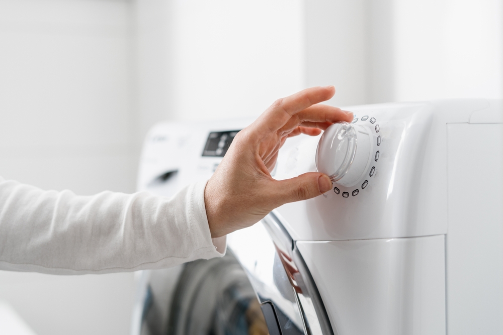
Tips
Behovet av en ny tvättmaskin
Ett behov av en ny tvättmaskin kan ha flera olika orsaker. Kanske har din gamla helt enkelt gått sönder eller så fungerar den fortfarande, men uppfyller inte de kraven du har på en tvättmaskin. Idag finns det tvättmaskiner med många praktiska funktioner som kan vara riktigt hjälpsamma i vardagen. Om du bor trångt kan exempelvis […]
Read More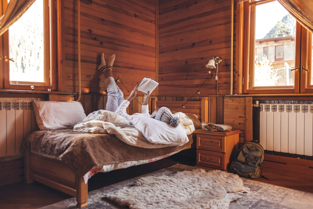
Tips
Bygg ett attefallhus på din tomt som gästhus
Det finns gott om saker du kan göra om du saknar sovutrymme i huset när gäster hälsar på. Du kan givetvis ställa fram ett par resesängar där det finns plats. Men ett ännu bättre val är att bygga ett attefallshus på tomten. Med ett attefallshus kan dina gäster få en egen lite stuga att hålla […]
Read More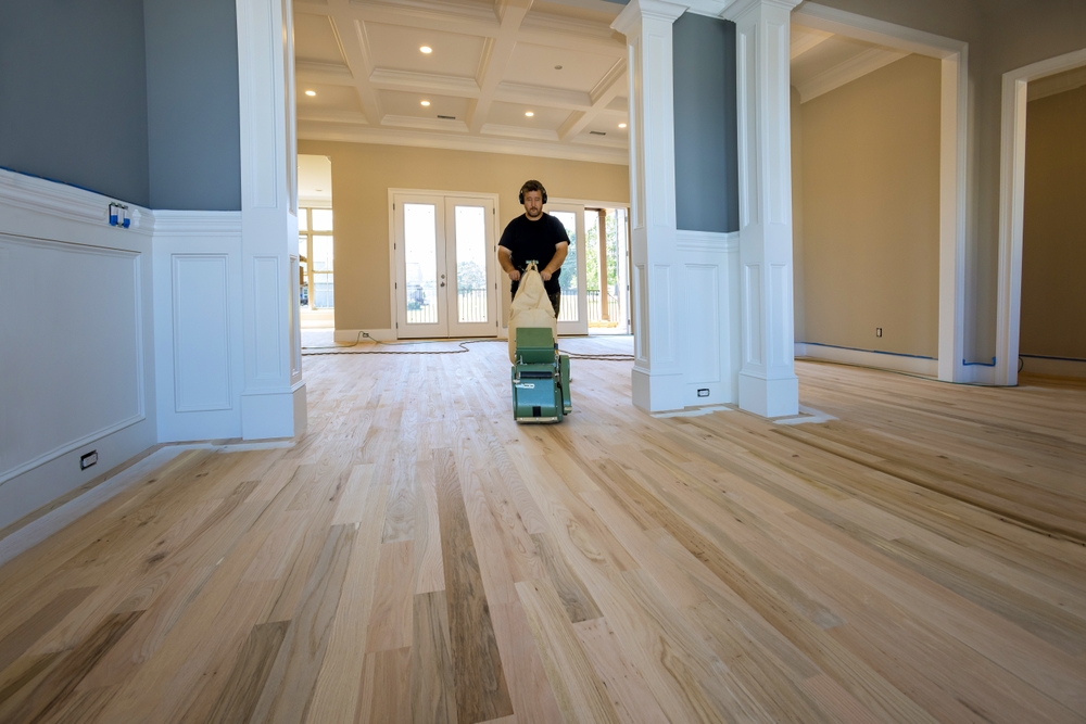
Renovering
Tips
Få ett snyggt golv i ditt vardagsrum genom golvslipning
I stället för att byta ut ditt trägolv kan du använda dig av golvslipning för att förbättra golvets kvalitet. Bland annat kan du få en snygg yta och ett nytt fräscht utseende på ditt golv med hjälp av Ångtvättbilen. Höj värdet på ditt hem Genom att fixa golvet i ditt hem kan du höja värdet […]
Read More
Design
Hur mobildesignen förändrades genom åren
Mobildesignen har kommit långt under åren. Det har varit en brant backe med stora förbättringar som har gjorts över åren. Vad som en gång började som en enkel telefon har nu utvecklats till ett avancerat verktyg som vi använder dagligen. Det första steget i mobildesign var den gamla klassiska mobiltelefonen som blev populär i början […]
Read More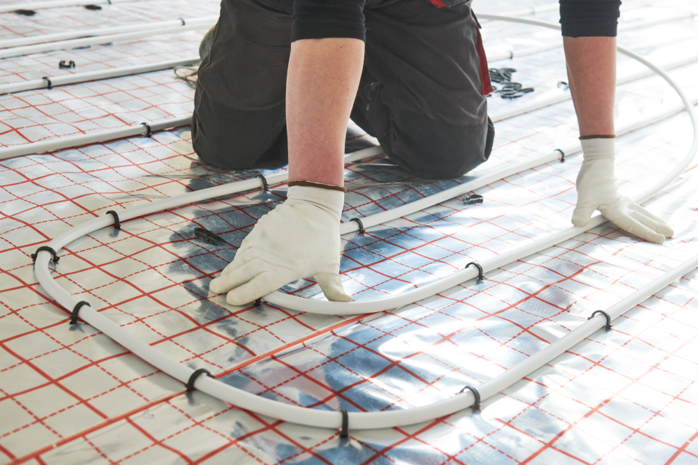
Renovering
Tips
Varför experter är ovärderliga vid golvvärmeinstallation
Golvvärme kan vid första anblicken verka enkelt. Lägg rör eller kablar, anslut till en värmekälla, och voilà! Men i själva verket är det mycket som kan gå snett om inte alla komponenter installeras korrekt. Experter har kunskapen och erfarenheten av att installera dessa system så att de fungerar effektivt och säkert. Ett felaktigt installerat system […]
Read More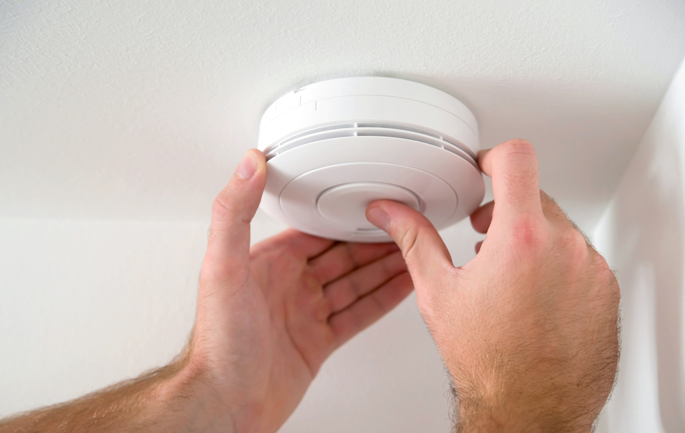
Tips
Hur ofta bör du byta dina brandvarnare och varför det är viktigt
Brandvarnare är en viktig del av varje hem, eftersom de kan varna dig i tid om det finns en brand och därmed ge dig en chans att snabbt agera och rädda dig själv och dina nära och kära. Även om de flesta av oss har brandvarnare hemma, är det många som inte är medvetna om […]
Read More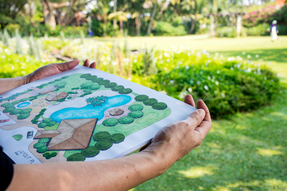
Design
Tips
Planera er trädgårdsdesign
Planera är ett viktigt steg när det gäller att skapa ett trädgård. Det är viktigt att ta hänsyn till dina önskemål och behov för att säkerställa att du skapar ett utrymme som du kommer att njuta av. Trädgårdsdesign kan vara ett kul och intressant sätt att skapa en unik utemiljö. Det kan låta som en […]
Read More